Project Detail
Adigudem Surface Irrigation Project (Gumselasa Dam)
In 1996, the Adigudem Dam was completed, and the next phase of the project involved constructing the irrigation canals downstream of the dam. Figure 1 illustrates the Adigudem Surface Irrigation Project, including the Gumselasa Dam.
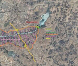
Figure 1 Adigudem surface irrigation project (Gumselasa dam), Tigray, Ethiopia
Enterprise: Sustainable Agriculture and Environmental Rehabilitation in Tigray Region (SAERT)
SAERT is a semi-governmental organization with its main office located in Mekelle, the capital city of the Tigray region in northern Ethiopia.
Construction Period
The construction of the irrigation system was carried out from February 1996 to November 1996.
Project Overview
According to the land survey data, the total farmland area was 136 hectares. The irrigation system designed for this farm utilized surface irrigation, which included:
- Primary/Principal Canal (trapezoidal)
- Secondary Canal (trapezoidal)
- Tertiary Canals (trapezoidal)
The primary and secondary canals were the main conduits, carrying water from the dam to the agricultural fields. The secondary canals were positioned along the extreme left and right boundaries of the farmland, while the tertiary canals were designed to distribute water into side furrows, running approximately perpendicular to the secondary canals towards the fields, as shown in Figure 1.
An existing waterway in the center of the farm serves as a natural drainage system, directing excess water downstream.
Canal Infrastructure
The irrigation system incorporated 400 concrete drop structures (canal falls), each with the following dimensions:
- Height: 1 to 1.7 meters
- Width: 0.9 to 1.2 meters
- Thickness: 0.3 meters
Both the upstream and downstream sides of the drop structures featured simple stone aprons (unmortared) for erosion protection. In addition, two large drop structures were built with stilling basins at the downstream side and a concrete apron at the upstream side to manage water flow and reduce erosion.
Visual Representation
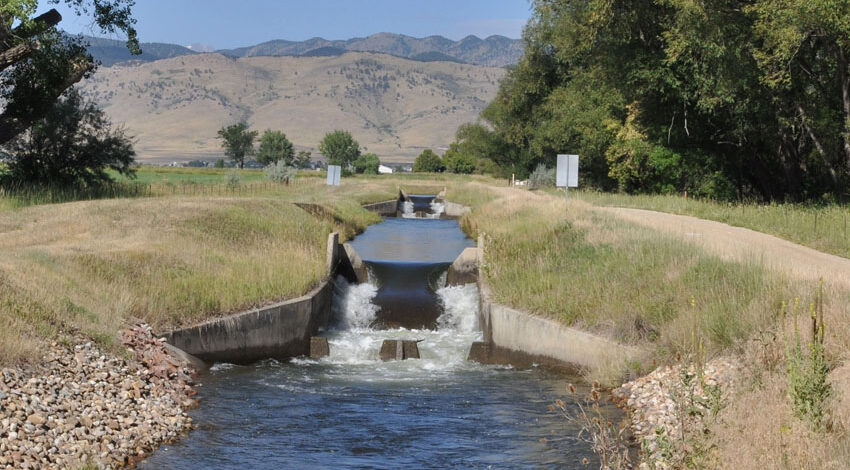
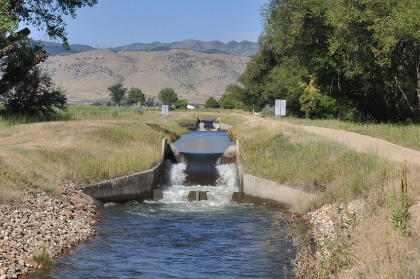
Figure 2 provides a conceptual visualization of the drop structures constructed at the Adigudem site. While the image is not an actual photo from the site, it serves to illustrate the type of drop structures used in the project.
This system has played a crucial role in optimizing water distribution and enhancing agricultural productivity across the project area.
Figure 2 Drop structure on Boulder Feeder Canal, NorthernWater.org.
Culverts
Three culverts were constructed along the irrigation system:
- Two culverts were installed along the route to provide passage for tractors, allowing them to move between different parts of the farm.
- The third culvert was designed to connect the primary canal to the right-side secondary canal, ensuring efficient water flow throughout the system.
The canals were primarily excavated by local communities, with minimal use of machinery, relying largely on manual labor for construction.
Turnouts (Division Boxes)
Several turnouts (also known as diversion boxes with small gates) were installed at the junctions of the secondary and tertiary canals. These turnouts were designed to control the flow of water and direct it to the required furrows.
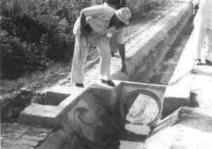
Figures 3 and 4 provide illustrations of the division boxes used in the Adigudem irrigation project, offering a visual representation of the turnout structures implemented at the site.
These structures played a key role in ensuring the proper distribution of water throughout the irrigation system.
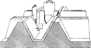
Figure 3 Division box /turnout (FAO).
Stilling Basin
Two large drop structures were equipped with stilling basins, each having approximate dimensions of 3m x 2m x 0.4m. These basins were designed to dissipate the energy of the flowing water, reducing erosion and ensuring smooth water flow.
Figure 5 illustrates a typical example of a stilling basin, demonstrating its design and function in the irrigation system.
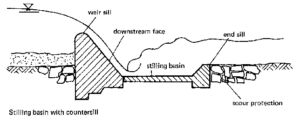
Figure 5 Typical Example of a stilling basin (www.nzdl.org)
[put_wpgm id=2]

